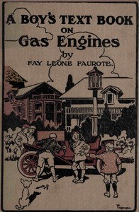
A boy's text book on gas engines
Related Books in Uncategorized

The Memoirs of François René Vicomte de Chateaubriand sometime Ambassador to England, Volume 1 (of 6)
Outing; Vol. XIII.; October, 1888 to March, 1889
Ricordi d'infanzia e di scuola
One Thousand Ways to Make Money
One Thousand Ways to Make a Living; or, An Encyclopædia of Plans to Make Money